
Pantile 2000
Britmet Lightweight Roofing pantile 2000 system is the only eave to ridge, granulated tile sheet on the market. Available from 1.53m to 6m in length and is manufactured to suit your rafter lengths, so no wastage, cutting or head lapping necessary.
Features & Benefits
- The lowest BBA approved tile effect sheet in the world
- 5 degree pitch
- 50-year warranty
- AA fire rating equal to traditional roof tiles
- Custom made to suit any rafter length
- Rapid installation time
Pantile 2000 Overview
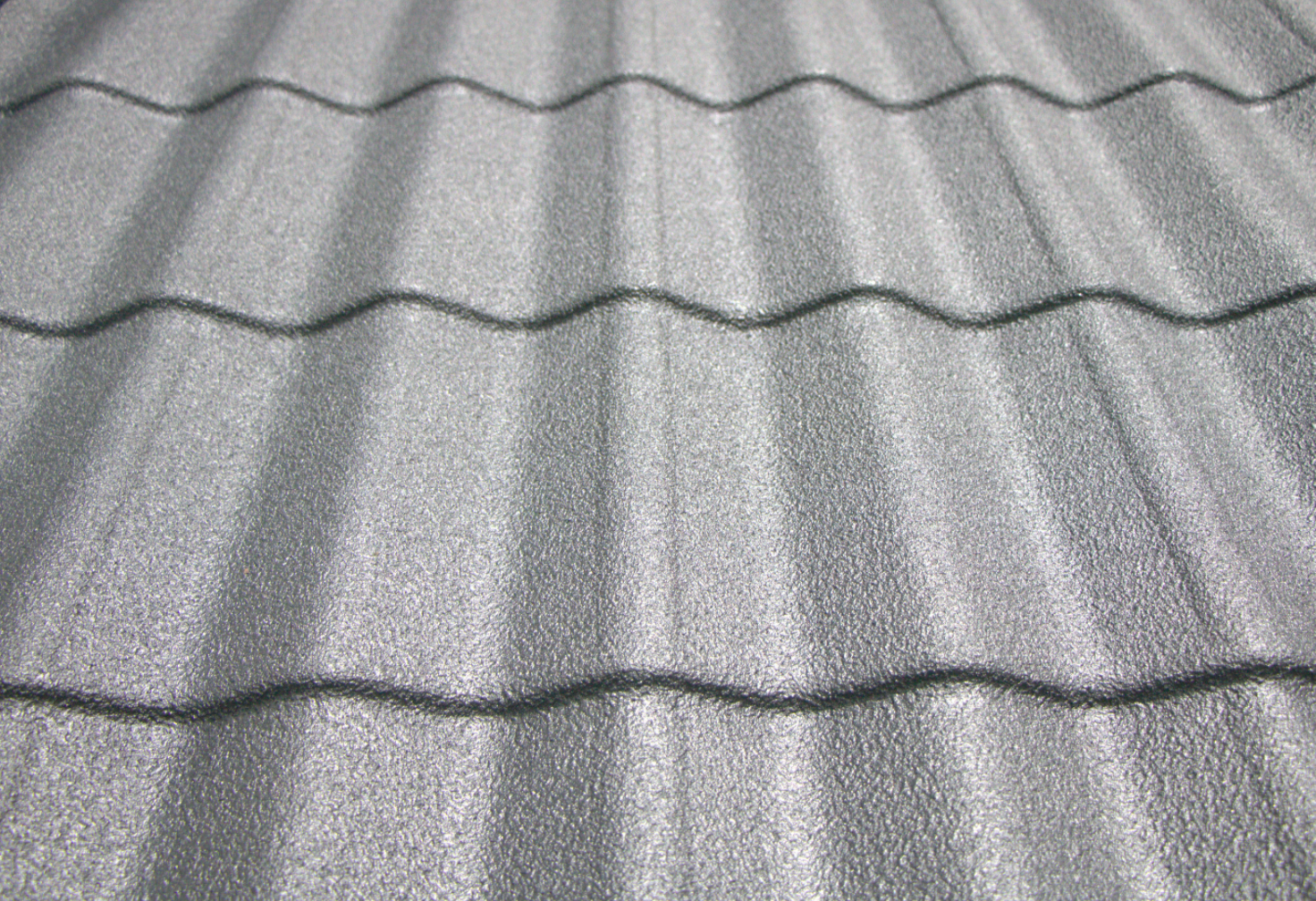
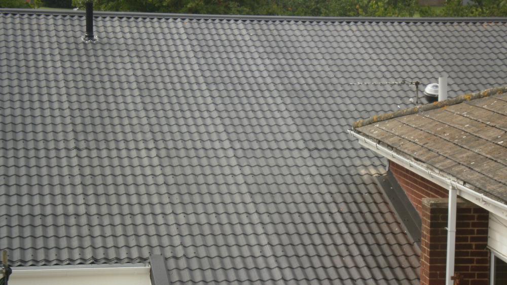
Britmet’s Pantile 2000 is the most innovative lightweight tile effect sheet in the construction industry. This market-leading product is the lowest BBA approved lightweight tile sheet in the world as it can be fixed to a roof pitch as low as 5°, backed with a weather penetration guarantee. Pantile 2000 is 1080mm (width) x custom length (up to 6m) and successfully achieves roof pitches from 5° - 70°. This unique tile is manufactured as a 'made to measure' product, meaning you can have Pantile 2000 made to your project's rafter length, reducing installation time by up to half.
Pantile 2000 is manufactured using the highest-grade Aluzinc steel, coated with pigmented mineral-filled acrylic. At a 0.9mm thickness gauge, Britmet’s Pantile 2000 is renowned for offering an elegant, secure, anti-vandal roof solution.
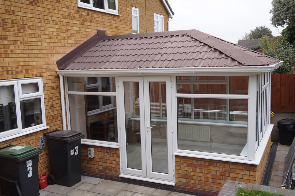
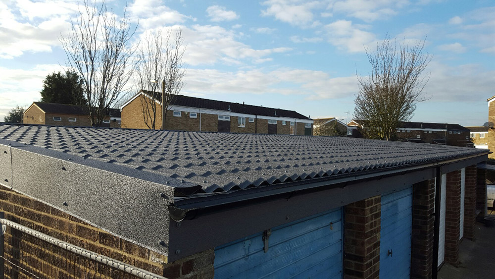
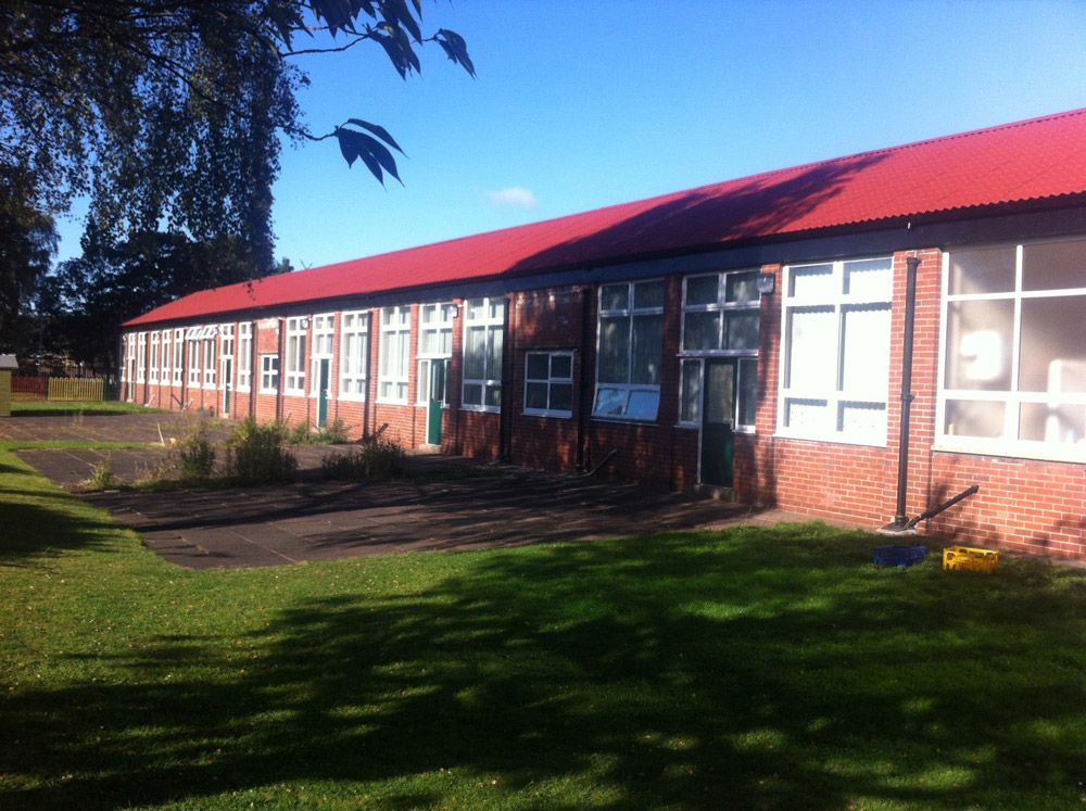
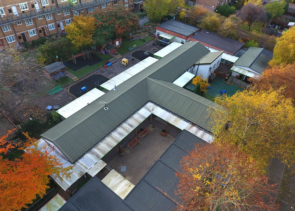
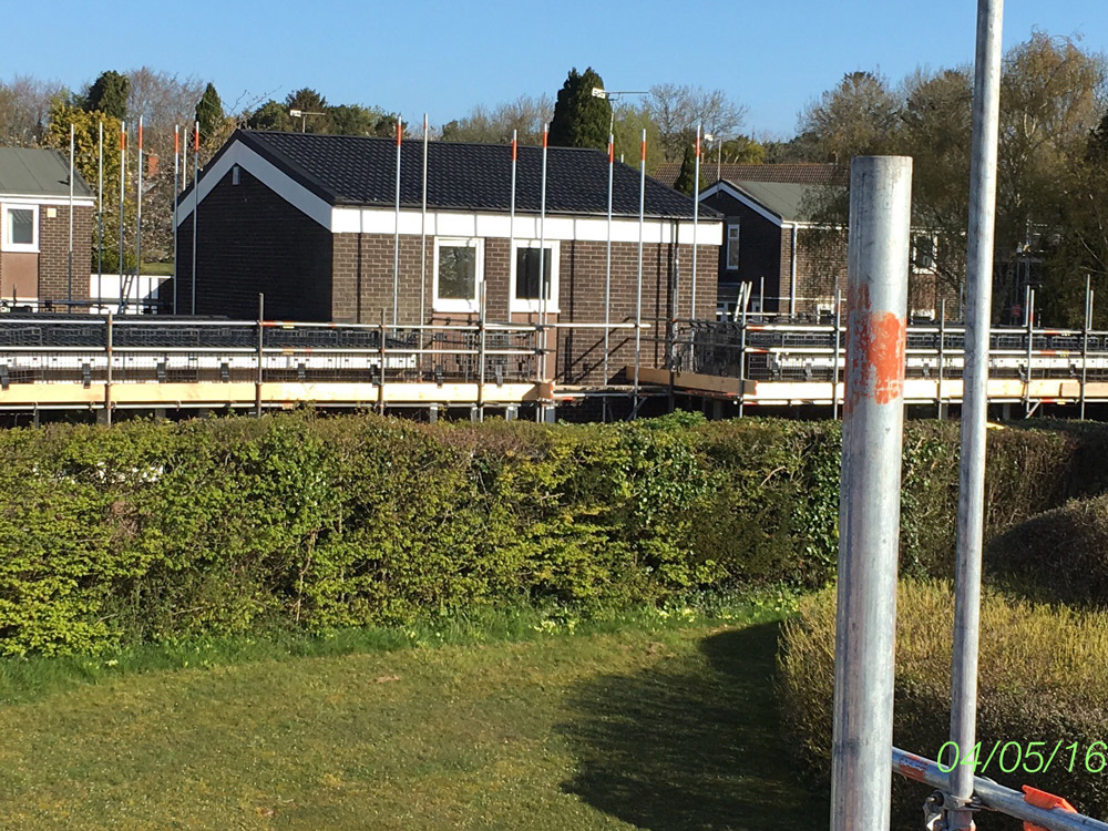
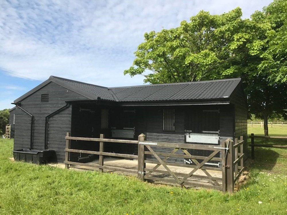
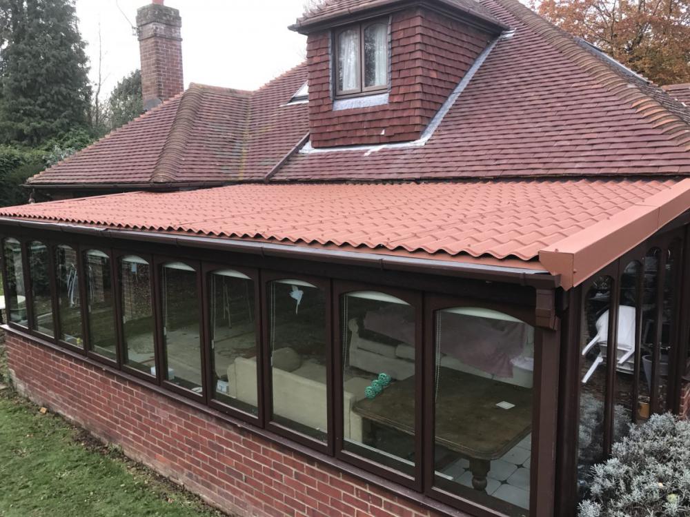
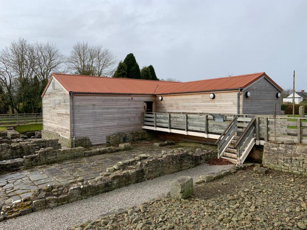
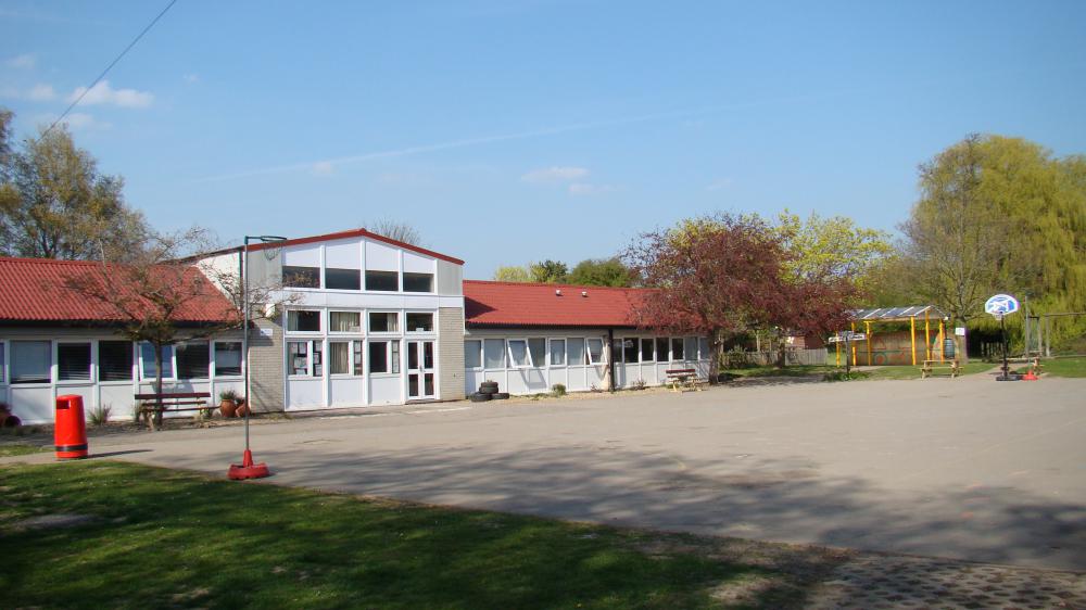
Originally manufactured as a replacement for old Asbestos roofs, the Britmet Pantile 2000 can be seen on garages, schools, hospitals and many more across the UK (see our Pantile 2000 case studies here).
Charcoal
Mid Grey
Terracotta
Tudor Brown
Antique Red
Sage Green
Pantile 2000 Brochure
Pantile 2000 Photo Gallery


Pantile 2000 Product Range


Pantile 2000 Case Studies
Pantile 2000 Technical Spec
| Min. pitch: | 5° |
| Max. pitch: | 70° |
| Overall width: | 1080mm |
| Cover width: | 1040mm |
| Side lap: | 40mm |
| Step: | 12mm |
| Purlin Centres (max): | 1500mm (0.7mm) & 1500 (0.9mm) |
| Individual tile module: | 300mm |
| Maximum sheet length: | 6m (over 6m for special orders) |
| Steel base: | 0.9mm |
| Weight as laid per m2: | 9kg & 11kg |
| Base coat: | Acrylic resin |
| Top coat: | Pigmented mineral filled acrylic |
| Colours available: | Charcoal, Terracotta, Mid Grey, Tudor, Brown, Antique Red, Sage Green |
| Chemical resistance: | Unaffected by normal pollution |
| Biological resistance: | Non toxic fungicide incorporated |
| Fire resistance: | AA classification equal to traditional roof tiles and slates |
| Fixings: | The contractor shall utilise the roofing manufacturers recommended fixings and sealant |
| Ventilation: | Roof ventilation should meet the recommendations of Building Regulations 1991 (amended ‘92, ‘94). Approved Document F2 1995 ‘Condensation in roofs’, BS 5250: 2021’ Control of condensation’. |
Pantile 2000 General Specification
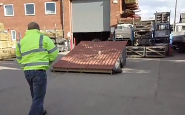
Handling and Storage:
Materials should be unloaded as close as possible to the
building where they are going to be installed. On-site,
packs should be stored on a firm, dry base away from
the possibility of damage. Sheeting packs should be laid
on pallets or bearers to allow ground clearance. 100mm
x 50mm Bearers should be arranged at the same
centres under each pack and must not exceed 2 packs
high. They must slope sufficiently to allow any rainwater
that may gather to drain away. A tarpaulin sheet should
cover the stacks, not touching the surface of the sheets,
which will allow for the circulation of air. To prevent
damage to the coating on installation, the sheets must
be lifted and not dragged from the pack. Damage to the
surface coating can be repaired with touch up paint.
(Supplied by Britmet.)
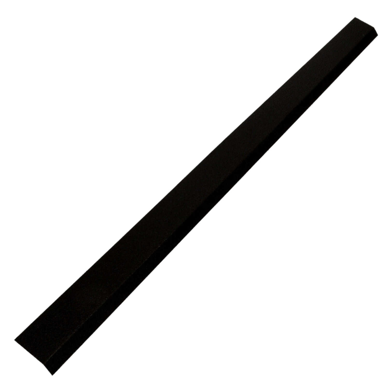
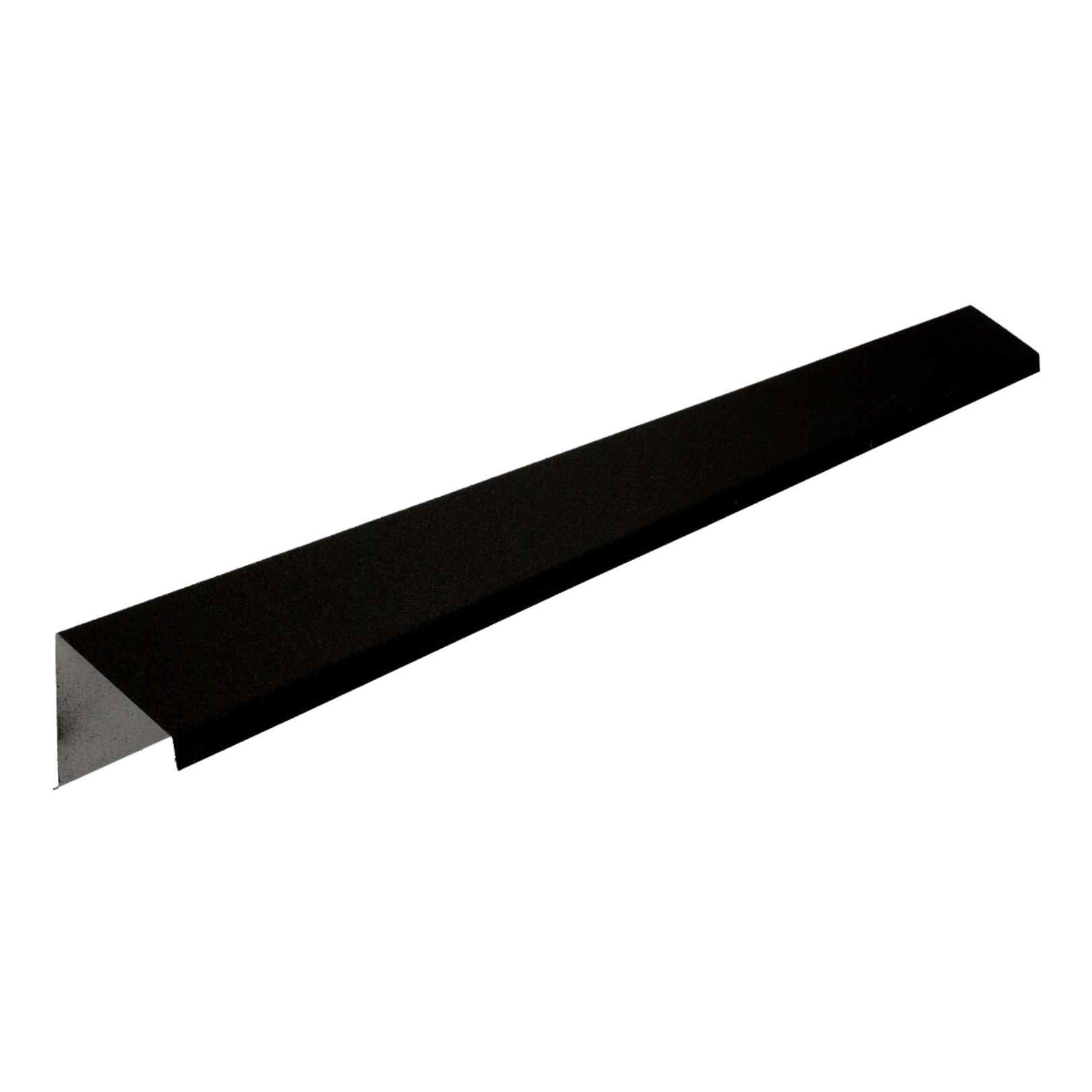
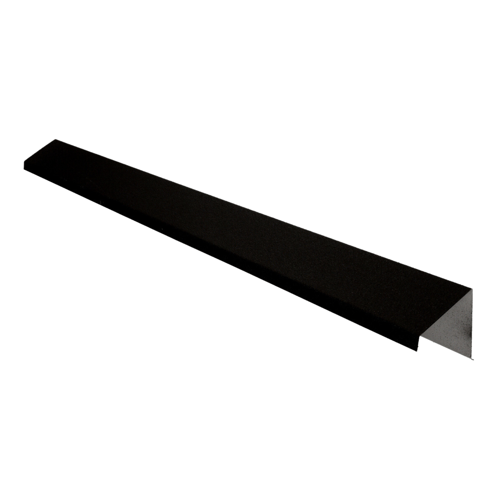
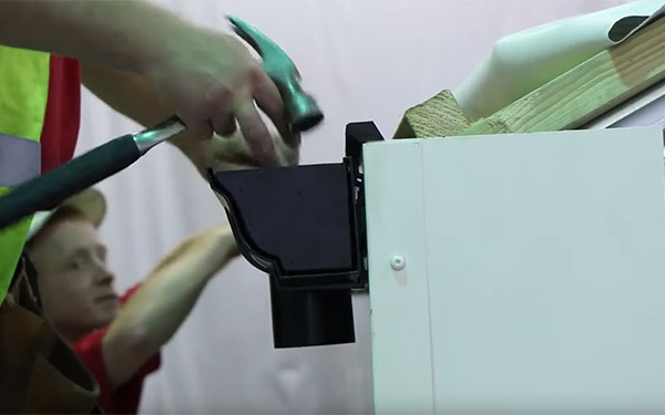
Eaves Drip Flashing:
Manufactured and coated in identical material to the
main roof covering. The minimum girth of 140mm, once
bent, fixed with secondary fixings and butt jointed.
(Manufactured length 2m).
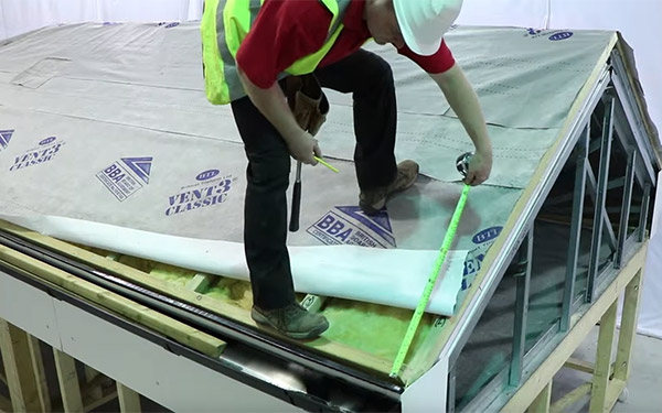
Underlay/Breather Membrane:
Note: if the purlin centres are greater than 900mm, lattice support wires should be used to eliminate the sagging of the breather membrane.
Purlins & Rafters:
Size and centres to be designed to suit Britmet Pantile
2000 tile effect roofing sheets.
Note: for timber purlins, the Tek screw/fastener must have a min. of 38mm penetration.
Note: steel & zed purlins should be a minimum gauge of 1.25mm.
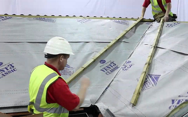
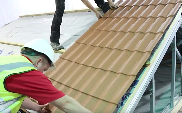
Pantile 2000 Tile Effect Roof Sheet:
All 0.9mm Pantile 2000 galvanised steel sheets are
coated using a pigmented mineral-filled acrylic coating,
available in 6 standard colours.
Note: All sheets MUST be laid from right to left.
Note: The first sheet must be laid so that its left-hand edge is perpendicular to the eave.
All sheets should be laid full length (ridge to eaves) where possible and securely fixed to the substructure.
Note: where an end/head lap is to be used, for a roof pitch of 10° or more allow a minimum lap of 75mm on the eaves sheet. For a roof pitch of 9° or less allow a minimum lap of 300mm on the eaves sheet.
Lapping requirements: lapping to be undertaken over supported areas only and all sheets must be mitred.
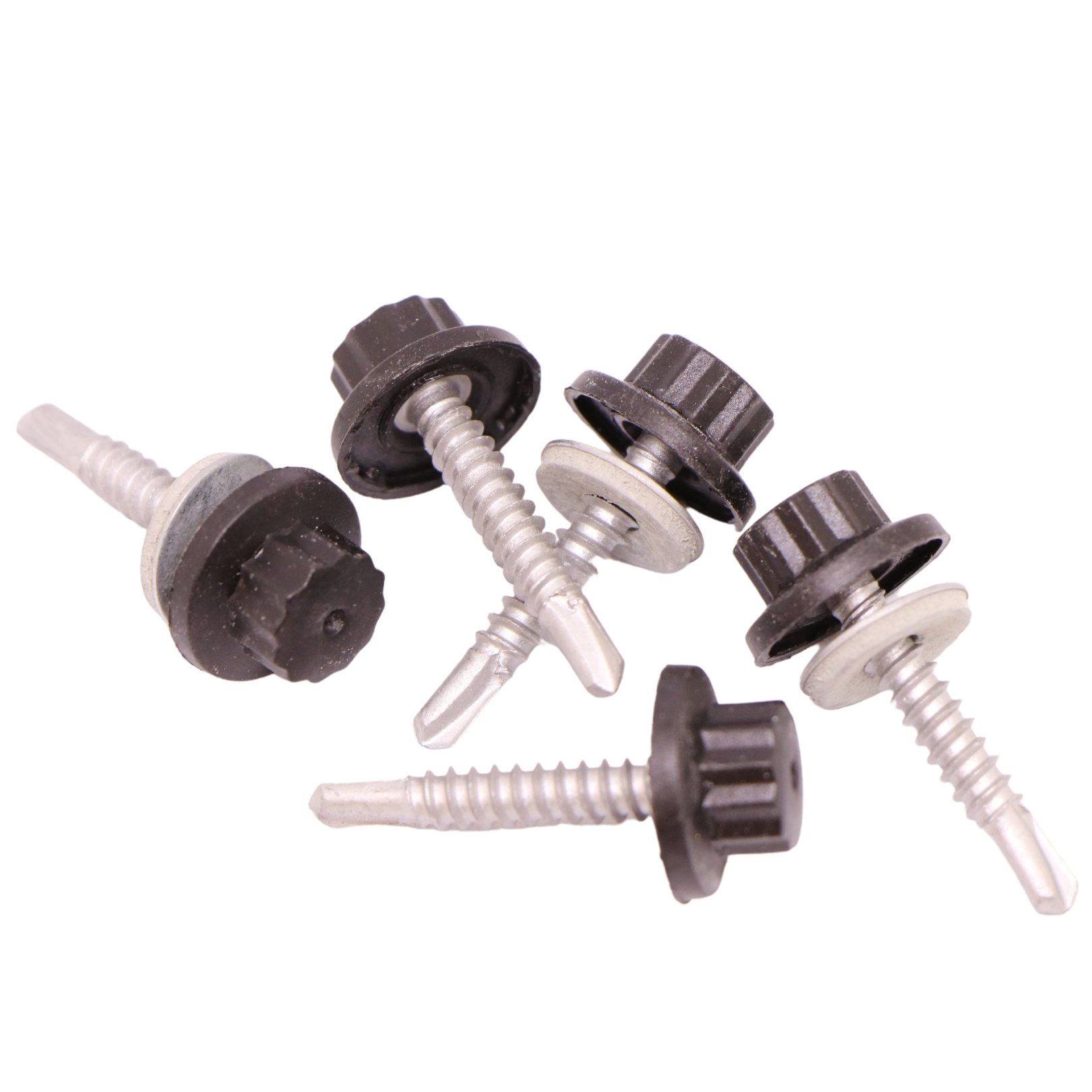
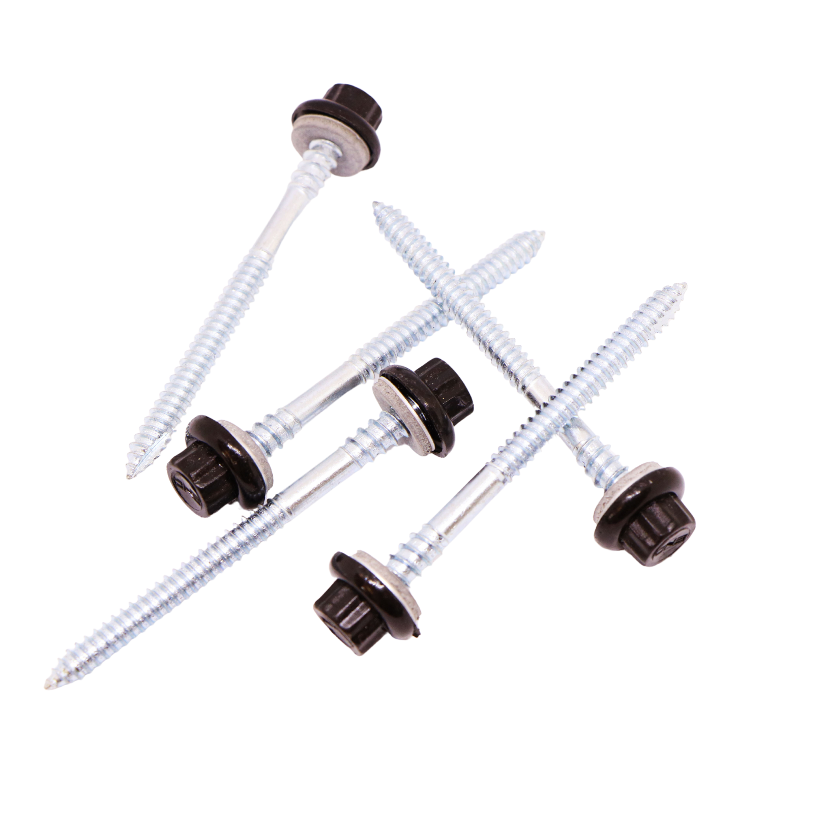
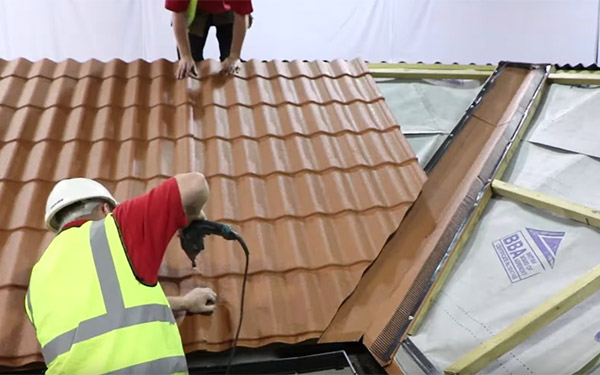
Fixings:
Main sheet fixings are to be fixed through the crown of
the profile using Tek screws with a cap colour to suit.
Fixings are to be placed at 3 per sheet, per purlin, except
for the eaves and ridge purlins which shall be placed at
4. Side lap stitching screws are be placed on every third
tile for roof pitches of 10° or more. For roof pitches of less
than 10°, they should be placed every second tile. Tek
screws are supplied by Britmet. (These quantities may
vary due to wind loading or other factors)
Note: For coastal areas, stainless steel screws must be used.
- All holes in the sheet must be drilled (not punched).
- All cutting must be made by a 110-volt nibbler or jigsaw and must take place on the ground or away from the material already fixed.
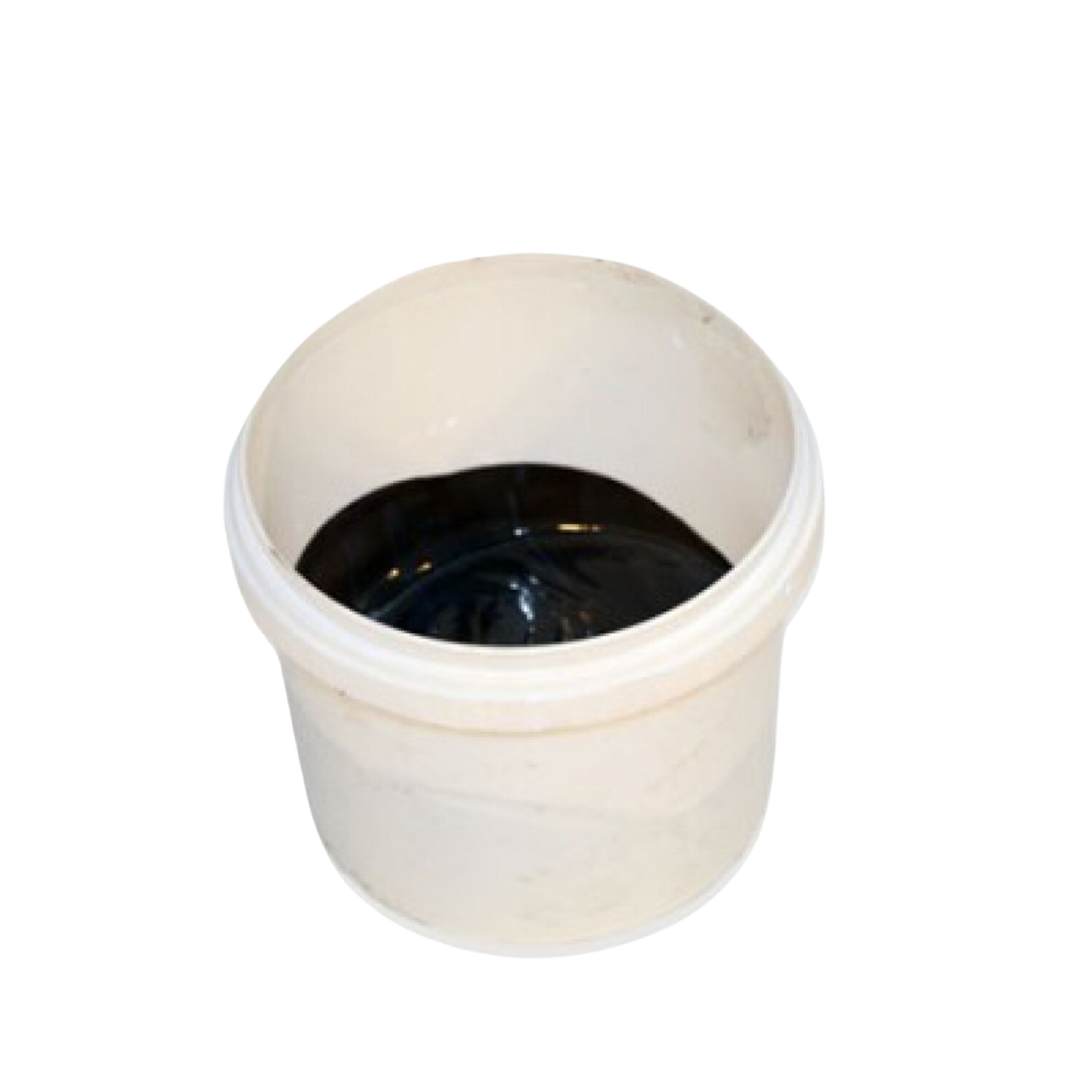
- All on site cutting to be immediately treated with Firtan, an anti-corrosive material, or touch up kit, provided by Britmet.
Note: After cutting, all swarf must be removed from the roof immediately.
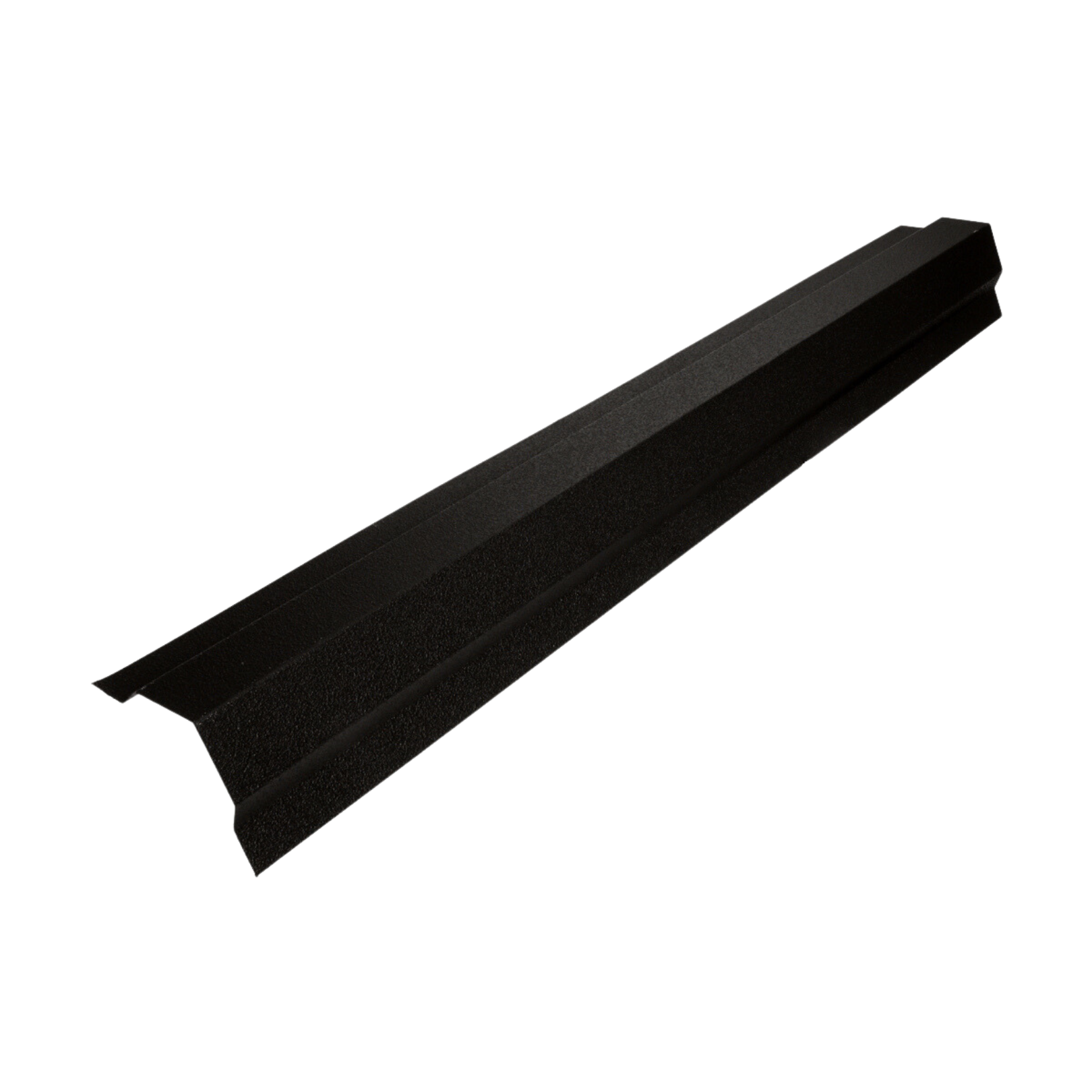
Ridge / Hip Flashing:
The minimum girth of 400mm, 5 times bent, butt-jointed
with 50mm under strip or lapped 50mm. (Manufactured
length 2m). 3 Fixings should be placed on each side. For
roof pitches of 10° or below, hip details should be sealed
using compriband expanding foam (B52 25mm x 10mm x
4m).
Barge / Mono Ridge Flashing:
The minimum girth of 340mm, three times bent, buttjointed
with 50mm under strip or lapped 50mm.
(Manufactured length 2m) 3 Fixings should be placed on
each side.
Valley Flashing:
The minimum girth of 420mm, three times bent, buttjointed
with 50mm under strip or lapped 50mm.
(Manufactured length 2m) 3 Fixings should be placed on
each side. For roof pitches of 10° or below, valley details
should be sealed using compriband expanding foam (B52
25mm x 10mm x 4m).
Pipe Flashing:
All standard vent pipes to be finished with Dektite pipe
flashing (Supplied by Britmet)
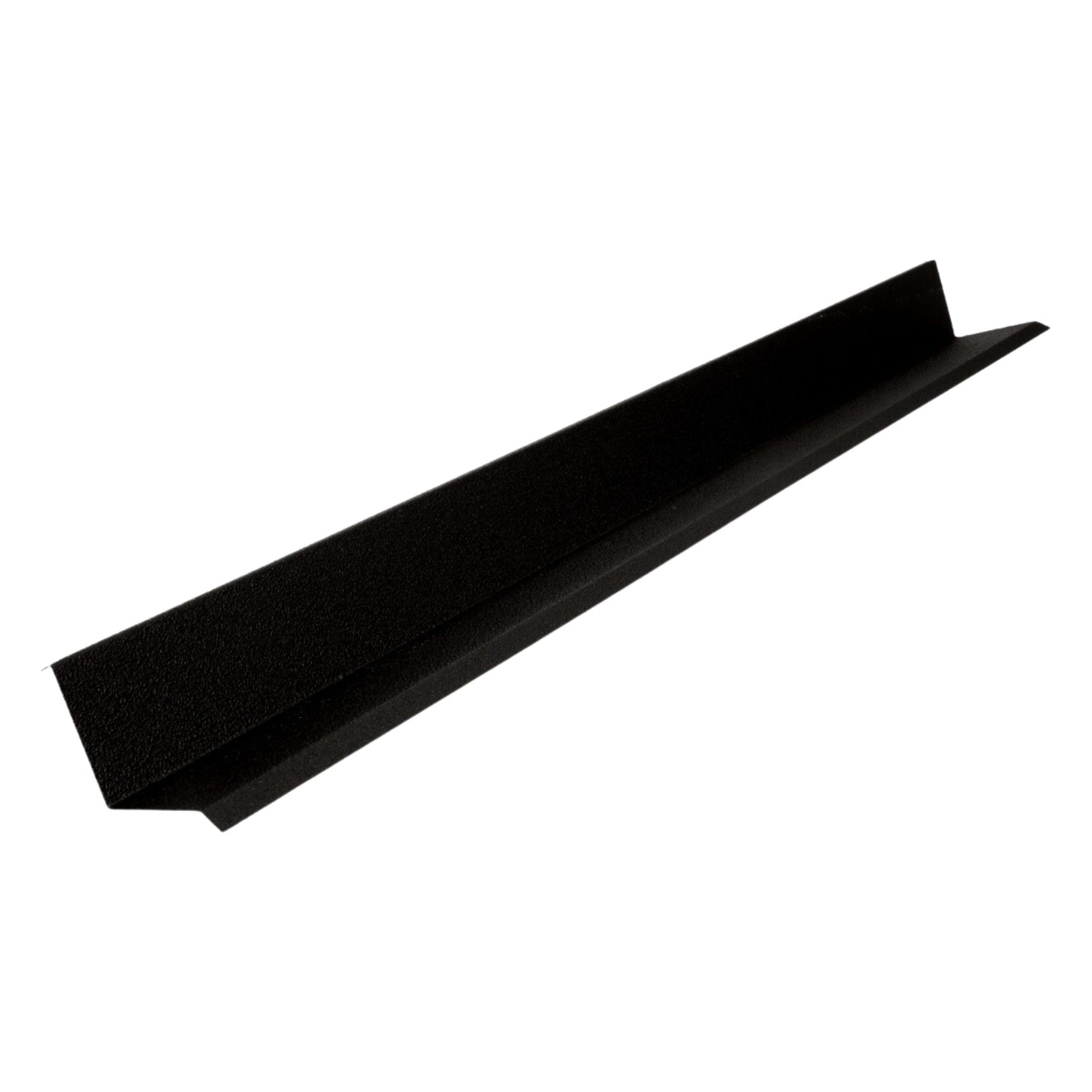
Upstand / Apron Flashing:
Upstand minimum girth is 350mm, twice bent. Apron
minimum girth is 300mm, three times bent. Butt jointed
with 50mm under strip or lapped 50mm. (Manufactured
length 2m.) 3 Fixings should be placed on each side.
Special Flashing:
All chimneys, vents, and special flashings are nonstandard
dimensions. Manufactured and coated in
identical material to the main roof covering or as required
by the client.
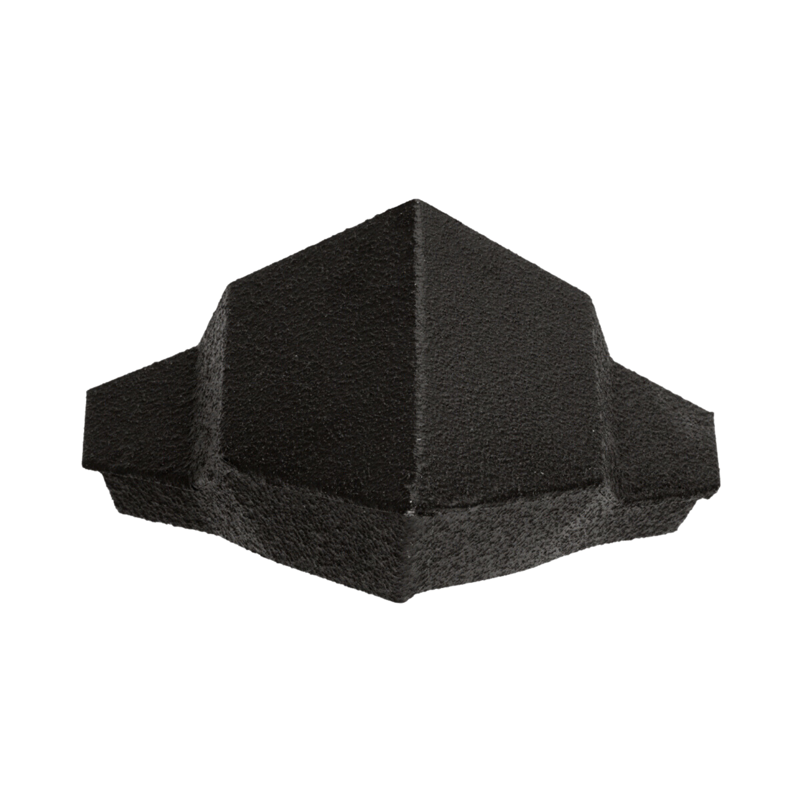
Flashing End Caps:
For ridge, barge and hips. Manufactured and coated in
identical material to the main roof covering.
Plastic Comb Fillers: (Ridge, Eaves, Hip and Valley)
Ridge and hip should be Tek screwed to the sheet. Eaves and valley should be Tek screwed to the flashing.
Note: For roof void ventilation at the eaves, use either soffit ventilation or the over fascia ventilating system, OFVS supplied by Britmet.
For duo roof pitches greater than 15° use OFVS 10. For duo roof pitches less than 15° use OFVS 25.
Sealant:
All sealant for side laps to be butyl mastic bead, code IDL
0303, grey or black.
- Pitches greater than 9° minimum mastic bead diameter 6mm
- Pitches less than 10° minimum mastic bead diameter 10mm
All work must be inspected upon completion and any damaged work should be replaced. All debris to be completely cleared from the roof area prior to the removal of the scaffolding.
Pantile 2000 NBS Spec
Pantile 2000 Installer Guide
Pantile 2000 Videos
Pantile 2000 Technical Drawings
| Ref | Description | Files |
| BLR-CAD-PANTILE2000-0005 | Pantile | DWG | JPG |
| SK-010 | Typical Ridge Detail. Steel Substructure | DWG | JPG |
| SK-011 | Typical Verge Detail. Steel Substructure | DWG | JPG |
| SK-012 | Typical Hip Detail. Steel Substructure. Cut Away Detail | DWG | JPG |
| SK-013 | Typical Mono Ridge Detail. Steel Substructure | DWG | JPG |
| SK-014 | Typical Ventilated Eaves Detail. Timber Substructure | DWG | JPG |
| SK-015 | Typical Ridge Detail. Timber Substructure | DWG | JPG |
| SK-016 | Typical Verge Detail. Timber Substructure | DWG | JPG |
| SK-017 | Typical Hip Detail. Timber Substructure. Cut Away Detail | DWG | JPG |
| SK-018 | Typical Hip Detail. Timber Substructure. Cut Away Detail | DWG | JPG |
| SK-019 | Typical Valley Detail. Timber Substructure. Cut Away Detail | DWG | JPG |
| SK-020 | Typical Mono Ridge Detail. Timber Substructure | DWG | JPG |
| SK-021 | Typical Eaves Detail. Steel Substructure. Insulation and Liner Tray | DWG | JPG |
| SK-022 | Typical Eaves Detail. Steel Substructure. Insulation and Liner Tray | DWG | JPG |
| SK-023 | Typical Hip Detail. Steel Substructure. Insulation and Liner Tray. Cut Away Detail | DWG | JPG |
| SK-024 | Typical Valley Detail. Steel Substructure. Insulation and Liner Tray. Cut Away Detail | DWG | JPG |
| SK-025 | Typical Verge Detail. Steel Substructure. Insulation and Liner Tray | DWG | JPG |
| SK-026 | Typical Mono Ridge Detail. Steel Substructure. Insulation and Liner Tray | DWG | JPG |
| SK-027 | Typical Lead Flashing Detail to Chimney. Chimney at Ridge | DWG | JPG |
| SK-028 | Typical Lead Flashing Detail to Chimney. Chimney within Roof Slope | DWG | JPG |
| SK-029 | Typical Apron Flashing Detail | DWG | JPG |
| SK-03 | Dimensional Information | DWG | JPG |
| SK-030 | Typical Upstand Flashing Detail | DWG | JPG |
| SK-031 | Typical Detail at Change in Slope | DWG | JPG |
| SK-032 | Typical Detail at Translucent Sheet. Plan and Section | DWG | JPG |
| SK-033 | Typical Aluminium Gas Vent Ridge Detail | DWG | JPG |
| SK-034 | Typical Air Vent Ridge and Soil Vent Ridge Detail | DWG | JPG |
| SK-035 | Typical Detail at a Box Gutter | DWG | JPG |
| SK-036 | Sunpipe | DWG | JPG |
| SK-04 | Standard Flashings. Ridge/Hip, Verge/Barge, Eaves Drip and Apron | DWG | JPG |
| SK-05 | Standard Flashings. Upstand, Mono Ridge, Eaves Fascial/ Soffit and Verge Fascia/Soffit | DWG | JPG |
| SK-053 | Pantile Tile | |
| SK-06 | Standard Flashings. Junction, Valley and Vent Ridge | DWG | JPG |
| SK-07 | Lapping Details. Side/Head Lap | DWG | JPG |
| SK-08 | Sheet Mitre Detail at Head Lap | DWG | JPG |
| SK-09 | Typical Ventilated Eaves Detail. Steel Substructure | DWG | JPG |